
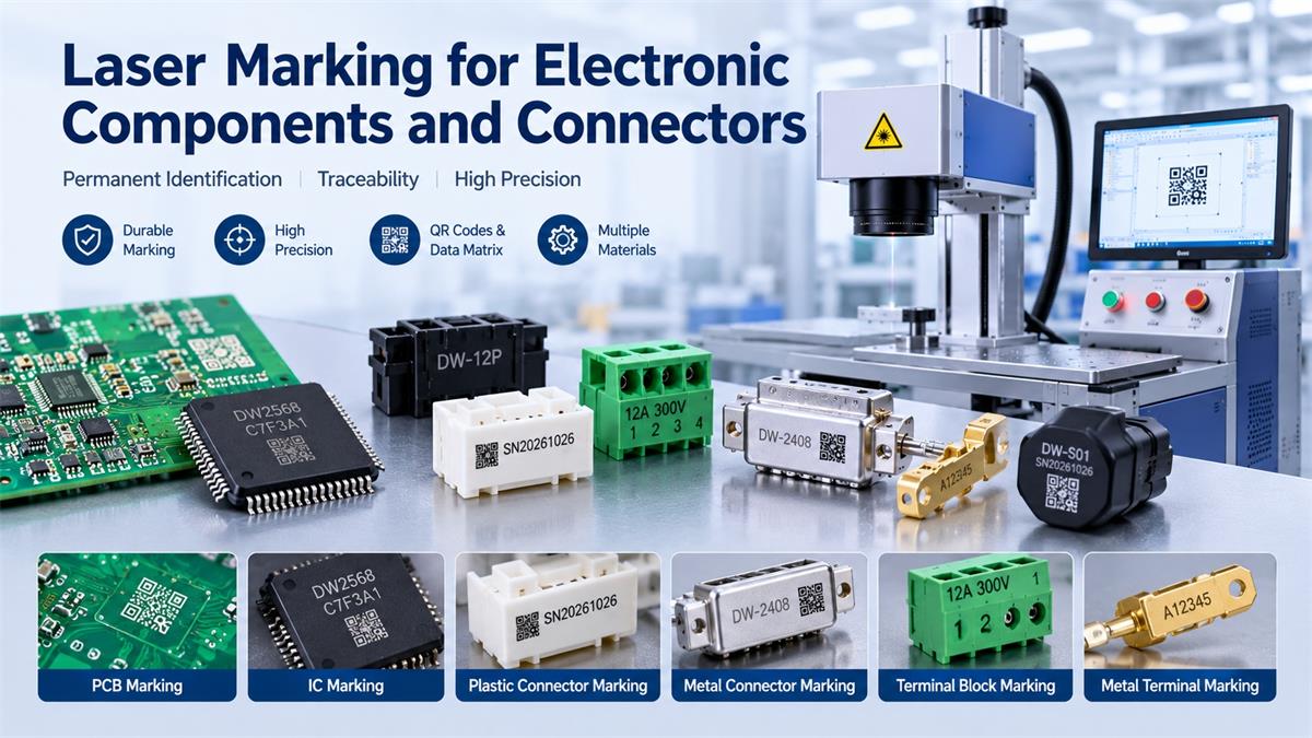
Laser marking for electronic components and connectors is widely used in electronics manufacturing for product identification, traceability, and quality control. From PCB boards and integrated circuits to electrical connectors, terminal blocks, and plastic housings, manufacturers need clear and permanent markings in increasingly limited spaces. Choosing the right laser marking machine depends mainly on the material being processed. For heat-sensitive plastic connectors and circuit boards, a 355nm UV laser marking machine is often a suitable option, while fiber laser systems are commonly used for metal terminals, housings, and other metallic components.
Unlike labels and ink printing, laser marking creates identification directly on the component surface without physical contact. This makes it suitable for small components that require precise positioning, consistent marking quality, and reliable product identification.
1. What Electronic Components Need Laser Marking?
Electronic manufacturers use laser marking for different identification requirements throughout the production process.
Common applications include:
-
Printed Circuit Boards (PCBs): Product codes, serial numbers, QR codes, and Data Matrix codes.
-
Electronic Connectors: Model numbers, manufacturer logos, polarity indicators, and traceability codes.
-
Terminal Blocks: Identification numbers, electrical specifications, and connection markings.
-
Integrated Circuits (ICs): Component identification, batch numbers, and production codes.
-
Sensors and Switches: Model information, logos, and manufacturing references.
-
Plastic Electronic Housings: Serial numbers, product specifications, and identification symbols.
-
Metal Terminals: Part numbers, batch codes, and permanent identification marks.
As electronic products become smaller, manufacturers increasingly need compact markings that remain readable without taking up valuable surface space.
2. Which Laser Type Is Best for Electronic Components?
There is no single laser source suitable for every electronic component. Fiber and UV lasers are two important options, and the correct choice depends on the material and required marking result.
Fiber Laser Marking for Metal Components
Fiber laser marking machines are commonly used for metallic electronic components.
Typical materials include:
-
Stainless steel
-
Aluminum
-
Brass
-
Copper
-
Steel and metal alloys
Typical applications include metal connector housings, conductive terminals, metal nameplates, and electronic equipment enclosures.
Fiber lasers use a 1064nm wavelength and are effective for direct marking and engraving on many metal surfaces.
For manufacturers processing large quantities of metal components, fiber laser marking offers a practical combination of marking speed, precision, and permanent identification.
UV Laser Marking for Plastic Connectors and PCBs
UV laser marking machines use a 355nm wavelength and are particularly useful for electronic components that require fine markings and controlled heat input.
Common applications include:
-
ABS, PC, PP, and other suitable plastic housings.
-
PCB and flexible PCB surfaces.
-
Electronic communication components.
-
Small plastic connectors and sockets.
-
Precision identification on sensitive materials.
Compared with conventional infrared fiber lasers, UV lasers can reduce thermal effects on many materials. This helps minimize unwanted burning, discoloration, and deformation.
UV technology is especially worth considering when marking small characters or 2D codes on heat-sensitive plastic components.
However, the final result depends on the exact plastic formulation, color, surface coating, and laser parameters. Sample testing is essential before production.
3. What Information Can Be Marked on Electronic Components?
Electronic components often have very limited marking areas. Manufacturers need to communicate essential product information while maintaining readability.
Common marking content includes:
Serial Numbers
Unique serial numbers help manufacturers identify individual components and track their production history.
QR Codes and Data Matrix Codes
2D codes can store identification information in a compact area. They are widely used for component traceability, production tracking, and automated inspection.
Product Model Numbers
Model numbers help distinguish different component specifications and configurations.
Manufacturer Logos
Laser marking can apply permanent logos and branding information directly onto component surfaces.
Batch Numbers and Production Dates
These markings help manufacturers identify production batches, investigate quality issues, and manage inventory.
For small connectors and electronic components, Data Matrix codes are often worth considering because they can encode information in a relatively compact marking area.
4. Key Challenges When Laser Marking Electronic Connectors
Marking electronic connectors requires more than selecting a laser with sufficient power. Their small dimensions, material differences, and functional requirements create several practical challenges.
Limited Marking Space
Connectors often have narrow surfaces and complex geometries. Large characters may not fit within the available marking area.
Solution: Use suitable optical configurations and carefully designed marking layouts. Test the minimum character size and code readability on actual components.
Heat Sensitivity
Some plastic connector housings can deform, discolor, or develop unwanted surface damage under excessive laser energy.
Solution: Consider UV laser technology and optimize power, frequency, scanning speed, and pulse parameters.
Different Material Compositions
Electronic connectors may combine plastic housings, copper terminals, metal shells, and surface coatings.
Solution: Select the laser source according to the specific material being marked. A mixed-material product may require different marking processes for different components.
High-Speed Production Requirements
Large electronics factories may need to mark thousands of components per shift.
Solution: Consider automatic feeding, conveyor systems, positioning fixtures, sensors, and production line integration.
Code Readability
A visually recognizable code is not necessarily a reliably readable code.
Solution: Evaluate code quality using an appropriate barcode verification system. Consider cell size, contrast, surface consistency, and the available scanner.
5. How to Choose a Laser Marking Machine for Electronic Components
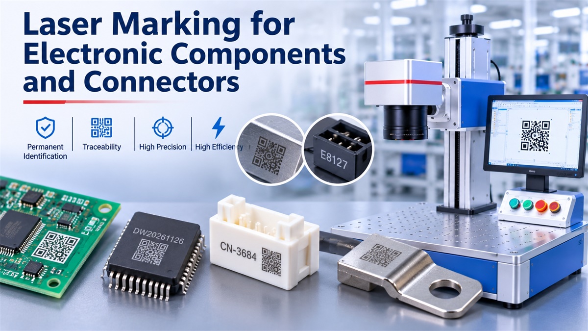
Before purchasing equipment, manufacturers should evaluate the following factors.
| Selection Factor | What to Consider |
|---|---|
| Material | Plastic, copper, aluminum, stainless steel, PCB |
| Laser type | UV or fiber laser |
| Marking content | Text, serial numbers, QR codes, Data Matrix |
| Marking size | Available surface area and character dimensions |
| Production volume | Manual workstation or automated line |
| Marking quality | Contrast, readability, and consistency |
| Integration | PLC, conveyor, sensors, and vision systems |
One important point is that higher laser power does not automatically produce better results on electronic components.
For delicate plastic housings and PCBs, controlled energy input and marking precision may be more important than maximum power.
For metal terminals and housings, fiber laser power should be selected according to the required marking speed, material, and depth.
6. Manual vs. Automated Laser Marking for Electronics Production
For small workshops and component manufacturers, a standalone laser marking machine may be sufficient.
Operators position components manually, load the marking design, and complete the process individually or in batches.
For larger manufacturing facilities, an automated system can improve production consistency.
Typical automation configurations include:
-
Conveyor-based automatic marking.
-
Sensor-triggered laser activation.
-
PLC communication with production equipment.
-
Automatic component positioning.
-
Vision-based positioning and inspection.
-
Automatic serial number and code generation.
For example, an electronic connector manufacturer can install a laser marking system after a molding or assembly station. When a component reaches the marking position, a sensor triggers the marking process.
The appropriate automation level depends on component dimensions, production speed, positioning accuracy, and available factory space.
7. Dowin Laser Marking Solutions for Electronic Components
Dowin offers different laser marking configurations for electronic manufacturing applications. The most suitable option depends on whether the main material is plastic, PCB, or metal.
UV Laser Marking Machine – For Plastic Connectors and PCB Applications
Dowin 355nm UV Laser Marking Machine
This model is worth considering for manufacturers marking plastic electronic housings, PCB surfaces, communication components, and small identification codes.
Its main specifications include:
-
Laser wavelength: 355nm.
-
Laser power: 3W, 5W, 10W, and 15W options.
-
Working area: 110 × 110mm, 200 × 200mm, or 300 × 300mm.
-
Repeated positioning precision: ±0.003mm.
-
Minimum marking line width: 0.01mm.
The main reason to consider this machine is its short-wavelength UV laser, which is suitable for applications requiring fine marking and reduced thermal effects.
Fiber Laser Marking Machine – For Metal Electronic Components
Dowin Portable Fiber Laser Marking Machine
For metal connector housings, copper terminals, aluminum components, and other metallic parts, a fiber laser marking machine is a more relevant option.
This machine offers:
-
20W, 30W, and 50W power configurations.
-
1064nm laser wavelength.
-
110 × 110mm standard marking area.
-
Optional 200 × 200mm and 300 × 300mm working areas.
-
Air-cooled operation.
It is suitable for manufacturers who need to mark identification numbers, logos, and other information on metallic components.
The important distinction is that these two machines address different material requirements. Choosing between them should be based on actual sample testing rather than simply comparing their power ratings.
For additional configurations, visit the Dowin Laser Marking Machine Collection.
8. Frequently Asked Questions
1. Can a laser marking machine mark electronic connectors?
Yes. Laser marking can be used on plastic connector housings, metal connector shells, copper terminals, and other suitable materials. The laser type must match the material.
2. Which laser is better for plastic electronic connectors?
UV laser marking is often a suitable choice because its 355nm wavelength allows precise marking with reduced thermal effects on many plastics. However, different plastic formulations respond differently, so sample testing is necessary.
3. Can laser marking be used on PCBs?
Yes. UV lasers are commonly used for PCB identification, including serial numbers, logos, and 2D codes. Processing parameters must be carefully controlled to avoid damaging circuit traces, solder masks, or nearby electronic components.
4. Can fiber lasers mark copper connectors?
Yes. Fiber lasers can mark copper components, but copper has different laser absorption characteristics from many other metals. Suitable laser parameters and sample testing are important for achieving consistent results.
5. Can laser marking machines generate serial numbers automatically?
Yes. With suitable marking software and production system integration, serial numbers can be generated automatically. Barcode data, batch information, and other variable content can also be incorporated into the marking process.
6. Is laser marking permanent on electronic components?
Laser markings are generally more durable than conventional ink printing or adhesive labels because they modify the material surface directly. Actual durability depends on the marking process, material, and subsequent environmental or mechanical exposure.
Conclusion
Laser marking plays an important role in electronic component identification and manufacturing traceability. From PCB boards and plastic connectors to metal terminals and electronic housings, different materials require different laser technologies.
For plastic connectors and heat-sensitive electronic components, UV laser marking is often the preferred starting point. For metal connector housings and terminals, fiber laser marking is generally more appropriate.
Before selecting equipment, manufacturers should test their actual components and verify marking contrast, code readability, production speed, and material compatibility.
Choosing the right laser marking solution helps improve identification consistency and supports more reliable electronic manufacturing processes.
Post time: Nov-04-2026
