
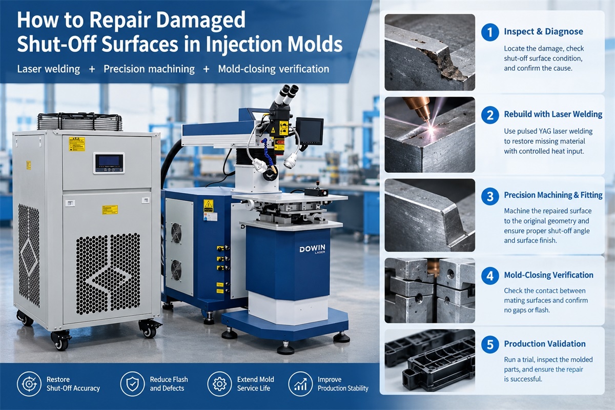
Damaged shut-off surfaces are a common cause of flash, poor parting-line quality, and inconsistent molding results in plastic injection molding. When the shut-off surfaces no longer fit together correctly, molten plastic can enter the resulting gap and form unwanted flash around the molded part. In more severe cases, repeated production may worsen the damage and increase mold maintenance costs.
Injection mold shut-off repair involves restoring the damaged sealing surfaces so that the mold closes correctly under operating conditions. Depending on the damage, the repair may require laser welding to rebuild missing material, precision machining or hand fitting to restore the original geometry, and mold-closing verification to confirm that the shut-off surfaces fit properly.
This guide explains how to identify shut-off surface damage, select an appropriate repair method, rebuild worn areas, and verify the results before returning the mold to production.
What Is a Shut-Off Surface in an Injection Mold?
A shut-off surface is a contact surface designed to prevent molten plastic from flowing into an area where it is not intended to enter. These surfaces are commonly found around core and cavity interfaces, side actions, holes, slots, and other mold features that require controlled separation between different regions of the cavity.
When the mold closes, the corresponding shut-off surfaces must fit together according to the mold design. If the surfaces are worn, chipped, scratched, or dimensionally incorrect, a gap may develop.
Even a small gap can allow plastic to penetrate the interface, depending on the resin viscosity, injection pressure, melt temperature, and local mold conditions.
Common symptoms of damaged shut-off surfaces include:
-
Flash or thin plastic fins along the parting line or around molded features.
-
Repeated flash in the same location despite normal process adjustments.
-
Visible wear, dents, scratches, or chipped edges on the shut-off surfaces.
-
Inconsistent contact between the core and cavity.
-
Localized gaps detected during mold inspection.
-
Increasing trimming and finishing requirements for molded parts.
Before starting a repair, it is important to distinguish actual surface damage from other causes of flash, such as excessive injection pressure, insufficient clamping force, incorrect process settings, or mold alignment problems.
Common Causes of Injection Mold Shut-Off Damage
1. Repeated Mold Closing and Wear
Continuous production exposes shut-off surfaces to repeated contact, friction, and mechanical loading. Over time, this can cause wear, especially in areas where the contact geometry is narrow or the local stress is high.
Wear may gradually reduce the height of the sealing surface or alter its original angle, allowing flash to develop.
2. Chipped Edges and Localized Material Loss
Thin shut-off edges can chip when molds are handled improperly, when hard debris becomes trapped between the mating surfaces, or when maintenance tools damage the steel.
A small missing section can create a localized gap even when the surrounding surfaces remain in good condition.
3. Scratches and Improper Polishing
Scratches, grinding marks, and uneven polishing can compromise the contact between mating surfaces. Aggressive polishing may also remove too much material, changing the original shut-off geometry.
This is particularly problematic when the surface requires a precise angle or a defined contact width.
4. Mold Misalignment or Uneven Clamping
Not every shut-off gap is caused by missing material. Misaligned mold components, worn guide systems, damaged inserts, or uneven clamping can prevent the surfaces from meeting correctly.
In these situations, welding the shut-off surface without correcting the underlying alignment problem may not solve the flash issue.
How to Diagnose a Damaged Shut-Off Surface
An effective injection mold shut-off repair begins with identifying the exact cause and location of the leakage path.
Step 1: Locate the Flash on the Molded Part
Inspect defective parts and record where flash appears. Compare several parts to determine whether the defect repeatedly occurs in the same location.
Consistent flash in one area may indicate a localized shut-off defect, while flash across multiple areas may suggest a broader alignment, clamping, or process issue.
Step 2: Inspect the Mold Surface
Clean the mold and examine the shut-off surfaces under suitable lighting and magnification. Look for chipped edges, worn contact areas, dents, scratches, and evidence of previous repairs.
A microscope or suitable inspection magnifier can help reveal small defects that are difficult to see with the naked eye.
Step 3: Check Contact and Alignment
Use an appropriate inspection method to evaluate the contact between mating surfaces. Depending on the mold design, this may include transfer marking, precision measurements, surface inspection, or controlled fitting checks.
Do not assume that every visible gap requires additional material. The gap may result from misalignment, incorrect angles, or interference elsewhere in the mold.
Step 4: Determine the Repair Allowance
Measure the damaged area and compare it with the intended mold geometry. Establish how much material must be restored and how much stock should remain for final machining or fitting.
This step helps prevent over-welding and reduces the risk of removing too much material during finishing.
Which Repair Method Is Best for Damaged Shut-Off Surfaces?
The appropriate repair method depends on the type of damage, the amount of missing material, the mold steel, and the required dimensional accuracy.
| Damage condition | Possible repair method | Main consideration |
|---|---|---|
| Minor scratches or surface marks | Precision polishing or stoning | Avoid changing the shut-off geometry |
| Small chips or localized material loss | Pulsed YAG laser welding followed by precision finishing | Restore missing material while limiting the repair area |
| Worn surfaces with measurable material loss | Laser welding, machining, and fitting | Rebuild the original profile accurately |
| Incorrect contact angle or excessive material removal | Controlled material rebuilding and precision machining, where feasible | Restore the intended shut-off angle |
| Mold misalignment or uneven closure | Alignment correction, component repair, or fitting | Welding alone will not correct the underlying cause |
| Extensive damage or severely deformed components | Engineering assessment and possible insert replacement | Evaluate repair feasibility and dimensional stability |
For localized damage, laser welding can be especially useful because it allows material to be deposited in a relatively small area. However, it is not a substitute for correcting structural damage, poor alignment, or an unsuitable mold design.
Step-by-Step: Injection Mold Shut-Off Repair Using Laser Welding
When a shut-off surface has lost material due to chipping, wear, or previous over-polishing, laser welding can rebuild the damaged area before precision finishing.
Step 1: Clean and Prepare the Damaged Area
Remove oil, grease, release agents, and other contaminants from the repair zone. Carefully inspect the damaged steel and determine whether the defect extends below the visible surface.
If cracks or deeper structural defects are present, assess them before proceeding. The repair method must address the actual defect rather than simply covering its appearance.
The amount of surface preparation should be controlled to avoid unnecessarily removing sound mold material.
Step 2: Select Compatible Filler Material
Choose filler wire that is compatible with the mold steel and the intended service conditions.
Important factors include:
-
Base steel composition and hardenability.
-
Required hardness and wear resistance.
-
Crack sensitivity during welding and cooling.
-
Compatibility with subsequent machining and polishing.
-
Mold operating conditions and expected service life.
Using an unsuitable filler can lead to cracking, excessive hardness, difficult finishing, or premature wear.
Step 3: Rebuild the Missing Material
A pulsed YAG mold repair laser welding machine can deposit filler material onto localized damaged areas. The operator should control the pulse energy, pulse duration, spot size, and deposition sequence according to the steel grade and the geometry of the shut-off surface.
For narrow shut-off edges, excessive heat input can cause edge melting or distortion. Large deposits can also increase finishing time and make the original profile more difficult to recover.
A better approach is to rebuild the damaged region in controlled increments, leaving a suitable finishing allowance.
The objective is to restore the material needed for machining—not to create the final sealing geometry directly through welding alone.
Step 4: Allow the Repair to Stabilize
After welding, assess the repair according to the mold steel, filler material, and welding procedure. Some materials or repair conditions may require controlled cooling or additional heat treatment, while others may not.
Avoid applying an identical cooling or heat-treatment procedure to every mold steel. Follow the material-specific requirements and evaluate the risk of cracking, residual stress, or hardness changes.
Step 5: Machine the Repaired Surface
Once the welded area is ready for finishing, restore the intended shut-off geometry.
Depending on the mold design and the amount of material deposited, finishing may involve precision grinding, milling, EDM, stoning, or localized polishing.
Pay particular attention to:
-
Shut-off angle and contact width.
-
Surface flatness or profile accuracy.
-
Edge sharpness where required by the design.
-
Height relative to adjacent mold features.
-
Surface finish and dimensional tolerance.
Excessive hand polishing can remove material unevenly and recreate the very gap the repair was intended to eliminate.
Step 6: Inspect the Finished Surface
Inspect the repaired surface under magnification and compare its geometry with the drawing, a reference feature, or the corresponding mating component.
Check for surface discontinuities, remaining low spots, excessive material, and evidence of cracking or other defects.
If the shut-off geometry is critical, dimensional inspection should be performed using appropriate measuring equipment rather than relying solely on visual appearance.
How to Correct Mold Closing Gaps and Flash After Repair
Rebuilding the damaged surface is only one part of the repair. The mold must also close correctly and maintain the required contact under actual operating conditions.
Verify the Contact Between Mating Surfaces
After machining, conduct a controlled fitting check using a suitable contact-marking method or other inspection procedure appropriate for the mold.
The goal is to verify that the intended contact areas meet according to the mold design. A uniform contact pattern is not necessarily required for every shut-off geometry, so acceptance should follow the engineering specification.
If contact is concentrated at one edge or absent in the damaged region, investigate the surface geometry and alignment before returning the mold to production.
Check Mold Alignment and Component Movement
Inspect guide pins, guide bushings, slides, lifters, inserts, and other components that influence closure.
For molds with side actions or moving shut-off components, confirm that the mechanisms reach their intended positions without binding or excessive play.
If the mating components are misaligned, correct the mechanical issue before making further changes to the welded surface.
Confirm the Closure Under Appropriate Conditions
A mold may appear to fit correctly during bench inspection but behave differently when installed in the molding machine. Clamping conditions, mold temperature, component movement, and machine setup can influence the final result.
Verify mold closure according to the established maintenance procedure and the equipment manufacturer’s requirements. Avoid forcing the mold closed when interference is suspected.
Perform a Controlled Trial Run
Once the mechanical and dimensional checks are satisfactory, conduct a controlled molding trial.
Inspect the molded parts for flash in the repaired area and compare the results with the required quality criteria. If flash remains, investigate whether the cause is residual surface damage, alignment, clamping, venting, or process conditions.
Do not assume that increasing clamping force or reducing injection pressure is the correct solution until the cause has been established.
Common Mistakes During Shut-Off Surface Repair
Several mistakes can reduce repair quality or lead to recurring flash.
Over-welding the damaged area: Depositing too much material increases machining time and can introduce unnecessary heat. Rebuild only the material needed to restore the original geometry.
Ignoring the shut-off angle: A surface may look smooth but still fail to seal if its angle or contact width is incorrect. Geometry is more important than appearance alone.
Using filler material without checking compatibility: A hard or unsuitable weld deposit can be difficult to machine or may not provide the required wear resistance.
Polishing without measuring: Excessive polishing can lower the repaired surface and recreate the closing gap. Use controlled finishing and verify dimensions as work progresses.
Repairing the surface without checking alignment: If the core and cavity are misaligned, restoring one surface may not eliminate flash. Inspect the complete closing system.
Skipping the molding trial: A visually acceptable repair does not automatically guarantee production performance. Final validation should include appropriate closure checks and molded-part inspection.
How to Choose a Laser Welding Machine for Shut-Off Repair
For mold maintenance workshops, a pulsed YAG mold repair laser welding machine is worth considering when shut-off damage involves localized material loss, chipped edges, narrow sealing surfaces, or small worn areas.
When comparing machines, evaluate more than rated power.
-
Pulse control: The machine should provide suitable adjustment of pulse energy and duration for the mold steel and repair geometry.
-
Welding stability: Consistent energy delivery helps produce repeatable deposits.
-
Microscope visibility: Clear magnification improves control when rebuilding narrow sealing edges.
-
Filler wire compatibility: The machine and welding process should accommodate the filler materials required for the molds being repaired.
-
Repair range: Consider both fine localized repairs and the larger defects commonly encountered in your workshop.
-
Finishing requirements: Evaluate whether the repair can be completed with the available grinding, machining, EDM, and inspection equipment.
A 200W or 400W machine may be suitable for different repair requirements, but rated power alone does not establish which model will perform better on a particular shut-off surface. Compare the available pulse settings and test the machine using representative mold steel and damage conditions.
For workshops that frequently repair injection molds, a practical evaluation should include the quality of the rebuilt edge, the amount of post-weld machining required, and the consistency of the final mold-closing results.
Frequently Asked Questions
What causes flash after an injection mold shut-off repair?
Flash may remain because the repaired surface has an incorrect height or angle, the mating components are misaligned, or the mold is not closing as intended. Process conditions, clamping force, and other mold defects can also contribute. Inspect the repaired area and the complete closing system before deciding on further corrective action.
Can laser welding repair a worn injection mold shut-off surface?
Yes. Laser welding can rebuild localized areas where material has been lost due to wear, chipping, or previous machining. The deposited material must then be finished to the required geometry, and the mold should undergo appropriate contact and production verification.
Is laser welding suitable for hardened mold steel?
It can be suitable for certain hardened mold steels, but the result depends on the material composition, hardness, filler wire, and welding procedure. Some steels are more susceptible to cracking or heat-affected-zone changes than others. Confirm material compatibility and establish a suitable procedure before repairing critical surfaces.
Does every shut-off gap require laser welding?
No. Laser welding is appropriate when material must be added back to a damaged surface. If the gap is caused by misalignment, incorrect fitting, worn guides, or process conditions, those issues must be corrected instead. Minor surface marks may require only controlled polishing or stoning.
How do you confirm that an injection mold shut-off repair is successful?
Verify the repaired dimensions and surface condition, inspect the contact between mating components, and confirm that the mold closes correctly. Then perform a controlled molding trial and inspect the molded parts for flash or other defects. Acceptance should be based on the mold’s engineering requirements and production quality criteria.
Conclusion
Successful injection mold shut-off repair requires more than filling a damaged area. The repair must restore the original sealing geometry, maintain the intended contact between mating surfaces, and prevent flash under production conditions.
For localized chips, worn edges, and material loss, pulsed YAG laser welding can provide a controlled way to rebuild the damaged steel. Precision machining and fitting then restore the shut-off profile, while mold-closing checks and a controlled molding trial verify the result.
For mold makers and maintenance workshops, the most reliable process is to diagnose the cause of the gap, rebuild only the missing material, finish to the required geometry, and validate the repair under appropriate molding conditions.
Post time: Oct-23-2026
